5G NR Mobility – Measurements
byRahul Kaundalon
In RRC_CONNECTED, the UE measures multiple beams (at least one) of a cell and the measurements results (power values) are averaged to derive the cell quality. In doing so, the UE is configured to consider a subset of the detected beams. Filtering takes place at two different levels: at the physical layer to derive beam quality and then at RRC level to derive cell quality from multiple beams. Cell quality from beam measurements is derived in the same way for the serving cell(s) and for the non-serving cell(s). Measurement reports may contain the measurement results of the X best beams if the UE is configured to do so by the gNB.
The corresponding high-level measurement model is described below:
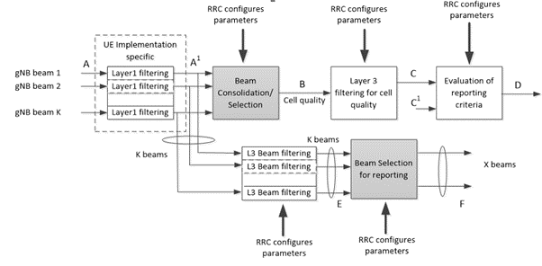
K beams correspond to the measurements on SSB or CSI-RS resources configured for L3 mobility by gNB and detected by UE at L1.
– A: measurements (beam specific samples) internal to the physical layer.
– Layer 1 filtering: internal layer 1 filtering of the inputs measured at point A. Exact filtering is implementation dependent. How the measurements are actually executed in the physical layer by an implementation (inputs A and Layer 1 filtering) in not constrained by the standard.
– A1: measurements (i.e. beam specific measurements) reported by layer 1 to layer 3 after layer 1 filtering.
– Beam Consolidation/Selection: beam specific measurements are consolidated to derive cell quality. The behaviour of the Beam consolidation/selection is standardised, and the configuration of this module is provided by RRC signalling. Reporting period at B equals one measurement period at A1.
– B: a measurement (i.e. cell quality) derived from beam-specific measurements reported to layer 3 after beam consolidation/selection.
– Layer 3 filtering for cell quality: filtering performed on the measurements provided at point B. The behaviour of the Layer 3 filters is standardised, and the configuration of the layer 3 filters is provided by RRC signalling. Filtering reporting period at C equals one measurement period at B.
– C: a measurement after processing in the layer 3 filter. The reporting rate is identical to the reporting rate at point B. This measurement is used as input for one or more evaluation of reporting criteria.
– Evaluation of reporting criteria: checks whether actual measurement reporting is necessary at point D. The evaluation can be based on more than one flow of measurements at reference point C e.g. to compare between different measurements. This is illustrated by input C and C1. The UE shall evaluate the reporting criteria at least every time a new measurement result is reported at point C, C1. The reporting criteria are standardised and the configuration is provided by RRC signalling (UE measurements).
– D: measurement report information (message) sent on the radio interface.
– L3 Beam filtering: filtering performed on the measurements (i.e. beam specific measurements) provided at point A1. The behaviour of the beam filters is standardised and the configuration of the beam filters is provided by RRC signalling. Filtering reporting period at E equals one measurement period at A1.
– E: a measurement (i.e. beam-specific measurement) after processing in the beam filter. The reporting rate is identical to the reporting rate at point A1. This measurement is used as input for selecting the X measurements to be reported.
– Beam Selection for beam reporting selects the X measurements from the measurements provided at point E. The behaviour of the beam selection is standardised and the configuration of this module is provided by RRC signalling.
– F: beam measurement information included in measurement report (sent) on the radio interface
Measurement reports are characterized by the following:
– Measurement reports include the measurement identity of the associated measurement configuration that triggered the reporting;
– Cell and beam measurement quantities to be included in measurement reports are configured by the network;
– The number of non-serving cells to be reported can be limited through configuration by the network;
– Cells belonging to a blacklist configured by the network are not used in event evaluation and reporting, and conversely when a whitelist is configured by the network, only the cells belonging to the whitelist are used in event evaluation and reporting;
– Beam measurements to be included in measurement reports are configured by the network (beam identifier only, measurement result and beam identifier, or no beam reporting).
Intra-frequency neighbour (cell) measurements and inter-frequency neighbour (cell) measurements are defined as follows:
– SSB based intra-frequency measurement: a measurement is defined as an SSB based intra-frequency measurement provided the center frequency of the SSB of the serving cell and the center frequency of the SSB of the neighbour cell are the same, and the subcarrier spacing of the two SSBs is also the same.
– SSB based inter-frequency measurement: a measurement is defined as an SSB based inter-frequency measurement provided the center frequency of the SSB of the serving cell and the center frequency of the SSB of the neighbour cell are different, or the subcarrier spacing of the two SSBs is different.
NOTE: For SSB based measurements, one measurement object corresponds to one SSB and the UE considers different SSBs as different cells.
– CSI-RS based intra-frequency measurement: a measurement is defined as a CSI-RS based intra-frequency measurement provided the bandwidth of the CSI-RS resource on the neighbour cell configured for measurement is within the bandwidth of the CSI-RS resource on the serving cell configured for measurement, and the subcarrier spacing of the two CSI-RS resources is the same.
– CSI-RS based inter-frequency measurement: a measurement is defined as a CSI-RS based inter-frequency measurement provided the bandwidth of the CSI-RS resource on the neighbour cell configured for measurement is not within the bandwidth of the CSI-RS resource on the serving cell configured for measurement, or the subcarrier spacing of the two CSI-RS resources is different.
Whether a measurement is non-gap-assisted or gap-assisted depends on the capability of the UE, the active BWP of the UE and the current operating frequency:
– For SSB based inter-frequency, a measurement gap configuration is always provided in the following cases:
– If the UE only supports per-UE measurement gaps;
– If the UE supports per-FR measurement gaps and any of the configured BWP frequencies of any of the serving cells are in the same frequency range of the measurement object.
– For SSB based intra-frequency measurement, a measurement gap configuration is always provided in the following case:
– Other than the initial BWP, if any of the UE configured BWPs do not contain the frequency domain resources of the SSB associated to the initial DL BWP.
In non-gap-assisted scenarios, the UE shall be able to carry out such measurements without measurement gaps. In gap-assisted scenarios, the UE cannot be assumed to be able to carry out such measurements without measurement gaps.
Reference – 3GPP